v1_0
Table of Contents
Shield Revision v1.0
Overview
v1.0 is a legacy board, and information here is only to inform.
Layout
| Surface Mount |
|---|
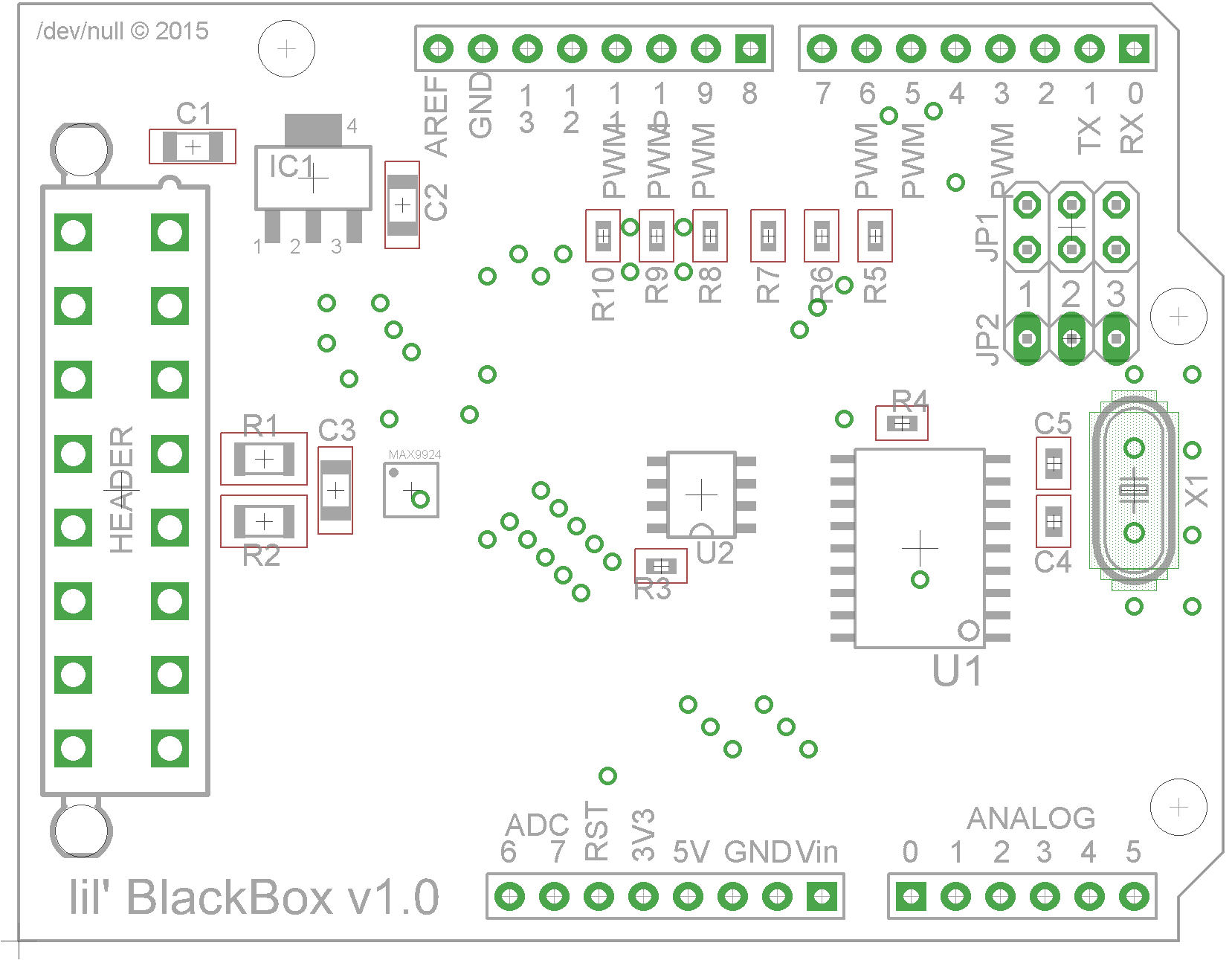 |
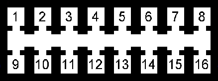
Pin Out
 |
||
|---|---|---|
| HEADER Pin # | Description | Schematic Net Name |
| Main Power | ||
| 1 | POWER IN | +12V |
| 9 | GROUND | GND |
| VR Sensor | ||
| 4 | VR+ | |
| 5 | VR- | |
| Digital I/O Inputs | ||
| 2 | Spare | S_IO |
| 3 | Cruise | C_IO |
| 10 | Brake | B_IO |
| 11 | Performance | P_IO |
| ADC I/O | ||
| 6 | ADC2 | |
| 7 | ADC1 | |
| 8 | ADC0 | |
| 15 | GROUND | GND |
| 16 | POWER OUT | +5V |
| CAN Bus | ||
| 13 | CAN Low | CANL |
| 14 | CAN High | CANH |
| SPARE | ||
| 12 | GROUND | GND |
Turbo RPM Curve
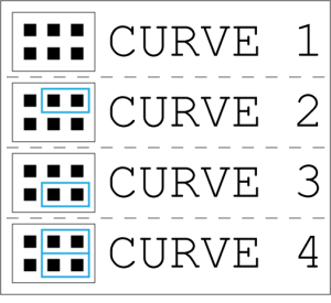
Selecting RPM curves is simple, just move the jumpers in to the corresponding pins for curve selection.
Curve 1 is the least aggressive curve.
Curve 4 is the most aggressive curve.
Performance Selection

Selecting the performance option is simple, just move the jumpers in to the corresponding pins for the desired selection.
Perf 1 is the default option.
Perf 2 is the more aggressive performance option.
Bill of Materials
| Name | Value | Size | Misc |
|---|---|---|---|
| Capacitors | |||
| C1 | 0.47uF | 1206 | 50V |
| C2 | 22uF | 1206 | 25V |
| C3 | 1000pF | 1206 | 500V |
| C4,C5 | 22pF | 0603 | 50V |
| Resistors | |||
| R1,R2 | 10K Ohm | 1206 | |
| R3 | 47K Ohm | 0603 | |
| R4,R5,R6,R7,R8,R9,R10 | 10K Ohm | 0603 | |
| ICs | |||
| IC1 | LM2940IMP-9.0/NOPB | SOT-223 | Main Power |
| IC2 | MAX9924UAUB/V+ | uMAX10 | VR |
| U1 | MCP2515-E/SO | SOIC-18 | CAN BUS |
| U2 | MCP2551-E/SN | SOIC-8 | CAN BUS |
| MISC | |||
| X1 | 16Mhz | HC49/S | CAN BUS |
| JP1 | 2×3 Header | Pitch: 2.54mm Height: 3.05mm | |
| JP2 | 1×3 Header | Pitch: 2.54mm Height: 3.05mm | |
v1_0.txt · Last modified: 2019/06/06 17:44 by hakcenter