Table of Contents
Standalone v2.0
Overview
HEADER pin outs are the same between the 2.0 and the Shield v1.1.
The standalone unit, has an integrated Arduino setup, compatible with the Arduino IDE for programming.
Layout
| Surface Mount |
|---|
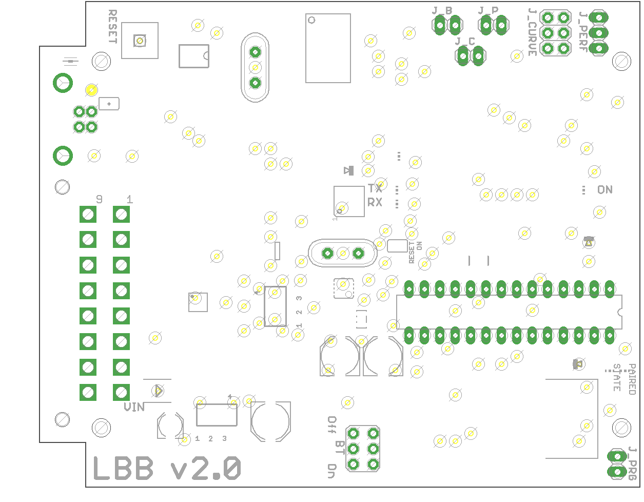 |
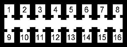
Pin Out
 |
|||
|---|---|---|---|
| HEADER Pin # | Description | Schematic Net Name | Wire Color |
| Main Power | |||
| 8 | POWER IN | +12V | Red |
| 16 | GROUND | GND | Black |
| VR Sensor | |||
| 4 | VR+ | Green/White | |
| 5 | VR- | Green/White | |
| Digital I/O Inputs | |||
| 2 | Spare | S_IO | Orange |
| 3 | Performance | P_IO | Orange |
| 10 | Brake | B_IO | Orange |
| 11 | Cruise | C_IO | Orange |
| ADC I/O | |||
| 12 | ADC2 | Blue | |
| 13 | ADC1 | Blue | |
| 14 | ADC0 | Blue | |
| 7 | GROUND | GND | Black |
| 15 | POWER OUT | +5V | Red/Blue |
| CAN Bus | |||
| 1 | CAN Low | CANL | Yellow |
| 9 | CAN High | CANH | Yellow/White |
| SPARE | |||
| 6 | GROUND | GND | |
Turbo RPM Curve
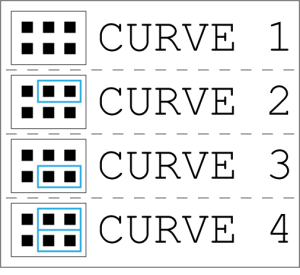 Selecting RPM curves is simple, just move the jumpers in to the corresponding pins for curve selection.
Curve 1 is the least aggressive curve.
Curve 4 is the most aggressive curve.
Performance Selection
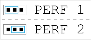
Selecting the performance option is simple, just move the jumpers in to the corresponding pins for the desired selection.
Perf 1 is the default option.
Perf 2 is the more aggressive performance option.